

26
2021
-
11
Discussion on Processing Technology of Disc Precision Gear Parts
Disc-shaped parts because of its part length and diameter ratio is very large, the lack of thickness of the parts lead to poor rigidity, processing technology is not good. When parts are processed, under the action of cutting force, clamping force, cutting vibration and other factors, it is easy to process deformation, and the accuracy cannot be guaranteed.
Disc-shaped parts because of its part length and diameter ratio is very large, the lack of thickness of the parts lead to poor rigidity, processing technology is not good. When parts are processed, under the action of cutting force, clamping force, cutting vibration and other factors, it is easy to process deformation, and the accuracy cannot be guaranteed.
Characteristics and processing difficulties of parts
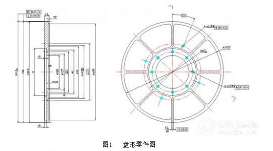
The disc gear parts are shown in Figure 1. The material of the parts is titanium alloy TC4-R, the outer diameter of the parts is φ201mm, and the total thickness of the parts is 9mm. The surfaces of the two ends of the part are respectively designed with relief grooves. One surface is evenly distributed with 6 fan-shaped relief grooves, and the other surface is provided with two annular relief grooves. The thickness of the middle part of the part is changed to 3mm. The number of gear teeth is 400, the modulus is 0.5mm, and the gear accuracy grade is 6. The maximum length-diameter ratio of this part is 1:67, which is a thin-walled part. It has the following characteristics:
(1) Insufficient wall thickness and poor rigidity of the parts. Under the action of clamping force or cutting force, the thickness of the parts is not enough to resist the action of clamping force, which is extremely easy to deform and cannot meet the requirements of dimensional accuracy, shape and position accuracy and gear accuracy.
(2) The quality of the parts is heavy, the outer diameter is large and thin, there are multiple relief grooves on both sides, the positioning, support, and focus points are small, and the positioning and clamping are difficult.
(3) Under the action of cutting force, especially the axial force, it is easy to produce vibration and deformation, which affects the dimensional accuracy, shape accuracy, gear accuracy and surface roughness of the parts.
Process measures and precautions
The design drawing of the disc gear parts is analyzed, the blank is processed to the finished part, the material removal rate is more than 60%, the larger the material removal rate, if the residual stress release problem can not be handled well, it is easy to cause the deformation of the parts during and after processing, which can not meet the design requirements.
In order to reduce the influence of part deformation on machining accuracy, the process is divided into roughing → aging → finishing → machining. Roughing is mainly to remove the surface of the large margin. Aging is the removal of residual stresses from finishing. The finishing of the positioning surface in finishing is the key process, which is prepared for the subsequent finishing and gear processing. Gear machining is arranged after finishing.
Each process of the process should consider the release of stress and control parts processing deformation, no matter which stage, the control of deformation as an important part of the processing of analysis and consideration, to ensure the machining accuracy of parts.
After the rough machining retains the finishing allowance, the basic structure of the parts has been fully processed and formed. Rough machining is the allowance for finishing. Under the premise of ensuring the finishing requirements, the allowance shall be minimized to ensure that the finishing will not cause large deformation after the allowance is removed. According to experience and practice, the outer circle shall be left with allowance of 0.3~0.4mm on one side and 0.15~0.2mm on the end face. At the same time, the flatness of the end face of the part should be limited during rough machining.
When finishing, the selection of positioning datum and machining accuracy are very important to ensure the accuracy of parts. Any high-precision surface processing must first select a good, good processing positioning datum. In order to ensure the accuracy of the 6 gear, the machining datum of the parts should be considered to coincide with the machining datum of the gear; the positioning datum is stable and reliable; the fixture structure of the positioning datum design is simple and easy to operate. According to these principles, this part selects a hole and an end face as the positioning datum. φ71mm step hole (datum A) and its end face (datum B) are design and assembly benchmarks, but the hole length is too short and the end face is too small. It is obviously inappropriate to use them as positioning references. Therefore, φ65mm hole positioning is selected, the positioning surface is relatively long, and it is also a through hole. The fixture is easy to manufacture and easy to load and unload parts. However, φ65mm holes have large tolerances and are not limited by form and position tolerances. Therefore, when selecting this hole as the positioning reference, it is necessary to improve the requirements for its dimensional accuracy and the coaxiality of the design reference φ71. According to experience and tests, the general hole tolerance is IT7, and the coaxiality is not more than 0.005mm, so as to eliminate the error caused by the non-coincidence of the process reference and the design reference. The selection of positioning end face, because the two large end faces are multi-grooved and are not a complete plane, its shape accuracy is not high, while the gear accuracy grade is grade 6 and the tooth direction error is 0.006mm. Therefore, the shape and position tolerance requirements of the end face as the positioning surface should be improved. According to practice, the flatness should not be greater than 0.005mm, and the perpendicularity requirements of the end face to the positioning hole φ65mm should not be greater than 0.005mm, the parallelism of the datum plane B shall not be greater than 0.005mm. At the same time, the runout value of the other end of the part facing the positioning hole shall be selected according to the gear accuracy grade look-up table. The φ65mm hole and a large end face are selected as the positioning reference plane to ensure the uniformity of the reference during finishing, gear processing, inspection and installation. Although the baseline was converted, the process measures were taken to meet the design requirements.
The precision of the parts is high, the processing of the positioning hole and the positioning end face is the key technology of the processing, mainly by the fitter and the lathe. The fitter shall cooperate with the lathe to ensure the form and position tolerance requirements of the positioning hole and the positioning end face of the part. First of all, the lathe vehicle positioning surface and a hole φ93mm require one-time processing. Then the fitter grinds the processed end surface to ensure a flatness of 0.005mm. The lathe vehicle positioning with the grinded end surface and φ93mm requires one-time processing of φ65mm, φ71mm, annular groove, end surface and maximum outer diameter φ201mm. This ensures the form and position tolerance requirements of the parts.
It is worth noting that the cutting force should be reduced in the machining process, the cutting amount should be controlled, and the parts should be prevented from vibrating. The clamping force is properly controlled to ensure that the parts are clamped and cannot be deformed. In order to control the stress and deformation of the parts during the clamping process, the end face table can be used to control. End face cutting should avoid assembly position, part positioning and pressing position; Flatness 0.005mm detection, because it is not a design requirement, it is the requirement of the process, and it is not necessary to have the measured data, as long as it can meet the final gear machining accuracy requirements. Through tracking the scene, it is found that as long as the positioning surface of the part is pushed on the inspection platform, the flatness of the part can meet the processing accuracy of the subsequent parts, and the method of hitting the end surface with a table on the platform can also be used together. This inspection method is easy to operate and master.
While ensuring the necessary hardness and accuracy of the hobbing fixture, the design of the fixture positioning surface and pressing surface is very critical. According to the structure of the part, in order to eliminate the deformation of the part during the pressing process due to the uneven positioning surface, so that the part can obtain accurate and reliable clamping, the annular solid surface near the tooth root at both ends of the part is selected as the positioning and pressing position. Therefore, a large annular groove should be machined on the positioning end face of the fixture and the pressing block to make way for the non-positioning part of the part, which can reduce the weight of the fixture and make the fixture easy to manufacture.
After the fixture is installed on the gear hobbing machine, the fixture should be adjusted. The positioning axis of the alignment fixture is concentric with the workbench; the positioning axis of the alignment fixture is perpendicular to the workbench; the positioning end face of the alignment fixture is parallel to the workbench. Note that the radial runout of the fixture is not greater than the 1/3 required for the radial runout of the machined parts. For the fixture with a long positioning part, it is necessary to correct two points and make the two points jump in the same direction, so as to avoid the fixture installation and the worktable are not perpendicular. The end face runout of the fixture is determined according to the radius of the fixture support end face, generally 0.006~0.01mm.
The installation of the parts is related to the accuracy of the processed gears. Therefore, the parts should be reliably fixed. At the same time, the outer diameter of the parts should be checked, and the outer diameter of the parts should be concentric with the fixture, and deformation should not occur under the condition of clamping the parts. The clamping condition of the workpiece can be checked by means of a table.
Due to the small gear modulus, high machining accuracy, the parts material is titanium alloy, this material has high strength, high hardness, impact resistance, easy hardening in processing, high cutting temperature and serious tool wear. It is a difficult material to process. AA grade carbide hob is selected and processed by multiple passes.
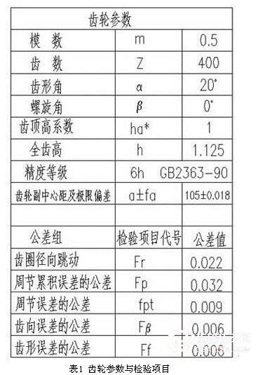
It can be seen from Table 1 that by using the gear measurement function in the Quindos measurement software on the three-coordinate measuring machine, the measurement of tooth direction, tooth shape, circumferential error, circumferential cumulative error and ring gear radial runout is completed at one time, and the measurement results can be output to meet the user's detection requirements.
The parts are made of titanium alloy, and the burrs are tough and difficult to remove. It is necessary to shovel the larger burrs and tooth surface bonds under a magnifying glass with a sharp tool, then repair the light locally, then use a regular gear deburring method to deburr, and finally use an ultrasonic cleaning machine to deal with it, so that the gear surface will be clean.
The above process method has been applied in many batches of parts on site and has been tested. The production problem has been solved for on-site production and processing. The qualified rate of parts can reach 99%. The processing of 300 parts (including Φ 181 and Φ 201 gears) is conservatively estimated to create millions of economic benefits. At the same time, it has also accumulated experience in processing precision components.
Related News

Address
Hutian Village, Chenzhai Town, Zhuji City, Zhejiang Province